|
Input files
|
WGCoupling.min,WGCoupling.ain
WGCoupling.zip
|
|
Description
|
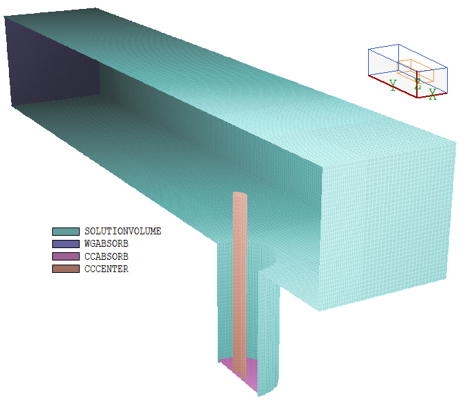
Simulation of a coaxial transmission line driving a waveguide in the TE10 mode. The top figure is a cutaway view of the system showing element divisions on region surfaces. The waveguide has height 1.75 cm in z and width 3.5 cm in x. A 10.1 cm length in y is modeled with a metal wall at the near end and a matched termination boudary at the far end. The cutoff frequency for the mode is fc = 4.286 GHz. At a drive frequency f = 6.00 GHz, the wavelength along the propagation direction (y) is c/sqrt(f^2- fc^2) = 7.145 cm.
The coaxial line has inner radius 0.10 cm, outer radius 0.50 cm and a dielectric with EpsiR = 2.0. The characteristic impedance is 68.3 ohms. The line connects to the waveguide a quarter wavelength from the metal boundary. The center conductor extends halfway across the waveguide. The transmission line has length 1.75 cm with a matched termination layer at the lower end. Radial current through this layer drives a TEM wave. The current density values in the Aether input file give a total current of 3.142 A. Half the current (1.57 A) is lost in the absorbing layer and the other half drives the TEM wave with power P = (1.57)^2*68.3/2 = 84.26 W. The goal of the calculation is to determine the S11 and S12 parameters for the network.
|
|
Results
|
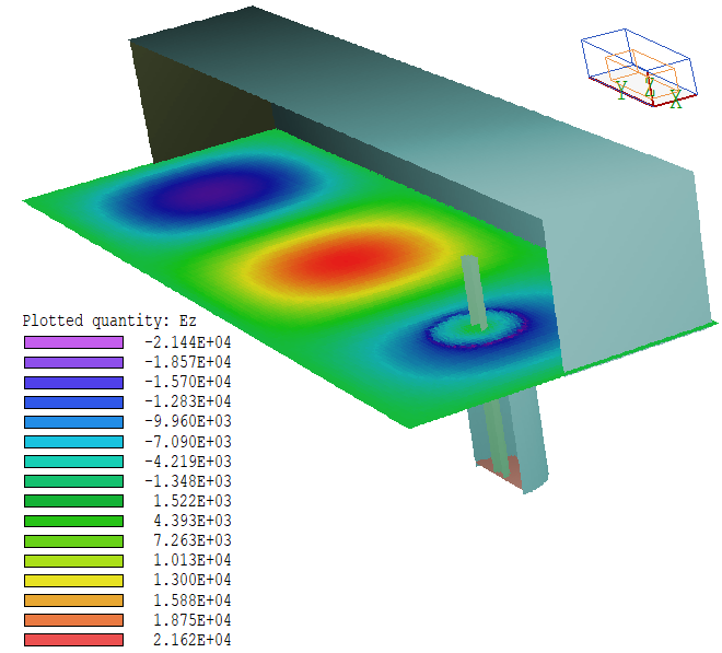
The central figure shows the electric field (Ez) of the TE10 mode at a single time. The excitation is primarily a traveling wave propagating in y with a small standing wave component. The maximum and minimum values of Ez in a scan along y gives a ratio of standing to travelling wave amplitudes of 0.178 corresponding to 96.7% absorption. The R/I port wave tool of Aerial gives a ratio of 0.19.
The parameter S21 is defined as the ratio of the value of a reference field in the output port (waveguide) with a matched termination to the field of the incident wave in the input port (transmission line). When the ports have different geometries, S12 is taken as the ratio of the square root of ratio of the power absorbed in the output port termination to the incident power of the input port. The incident power is 84.26 W and Aether calculates a power 78.38 W dissipated in the waveguide termination, yielding S21 = sqrt(78.38/84.26) = 0.9645. Because the coaxial line is not perfectly matched to the waveguide, we expect it carries a component of reflected wave. The parameter S11 is the ratio of the reflected to the incident field of the input port. Energy conservation implies that S11 = sqrt(1.000 - S21) = 0.1884.
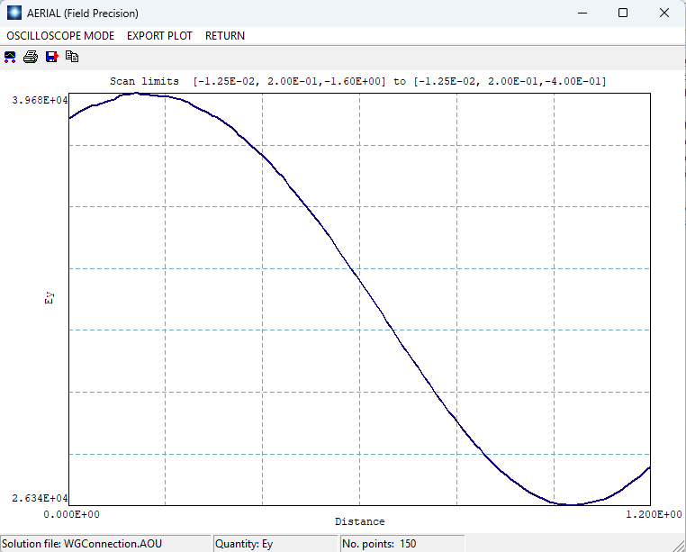
An alternate method to determine S11 is a direct measurement of the incident and reflected waves in the line. The bottom figure shows a scan along z of radial electric field. The maximum (39.68 kV/m) and minimum (26.34 kV/m) values imply a value of the standing wave ratio SWR = 1.506. This value is related to the S parameter by S11 = (1-SWR)/(1+SWR) = 0.506/2.506 = 0.202. The R/I port wave tool of Aerial gives S11 = 0.195. Both values are consistent with the value determined from S21.
|
|
Comments
|
A conclusion is that the system provides very good coupling to the waveguide. A useful direction for numerical modeling is to check whether the coupling is improved by shaping the tip of the coaxial line extension. The geometry, material properties and RF parameters are based on a ComSol benchmark example, Coaxial to Waveguide Coupling. Aether results are consistent with those listed in the Comsol report.
|